
# FAQs on Automate Kit
# 1. Where can I download the Automate App?
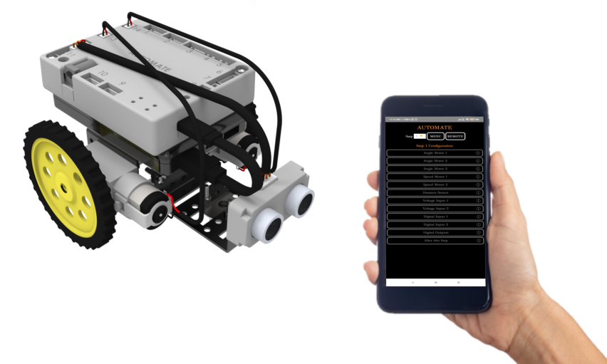
Automate App for Android and Windows can be downloaded from the KiMu's Automate Kit page.
# 2. How to connect the Automate App to the Control Unit?
Automate App can be connected to the Control Unit via WiFi or Cable.
# Connecting the app via WiFi:
Connect your device through WiFi (default)
- Wi-fi Name: AUTOMATE
- Password: automate
Control Unit should be powered on for the WiFi to be shown in the device.
# Connecting the app via cable:
Connect the device using a USB cable in case of Windows. For Android use the OTG adapters provided.
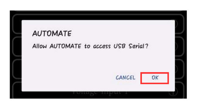
Enable the permission on the device to access the AUTOMATE app through USB/OTG.
Points to remember while connecting the device to the app:
- Turn off all the firewalls (eg. Anti-virus) before using the app on desktop/laptop.
- Turn off mobile data and other Wi-Fi connections before connecting the mobile to AUTOMATE Wi-Fi.
# 3. How to change WiFi setting in the Automate App?
Wi-Fi settings can be changed by following these steps
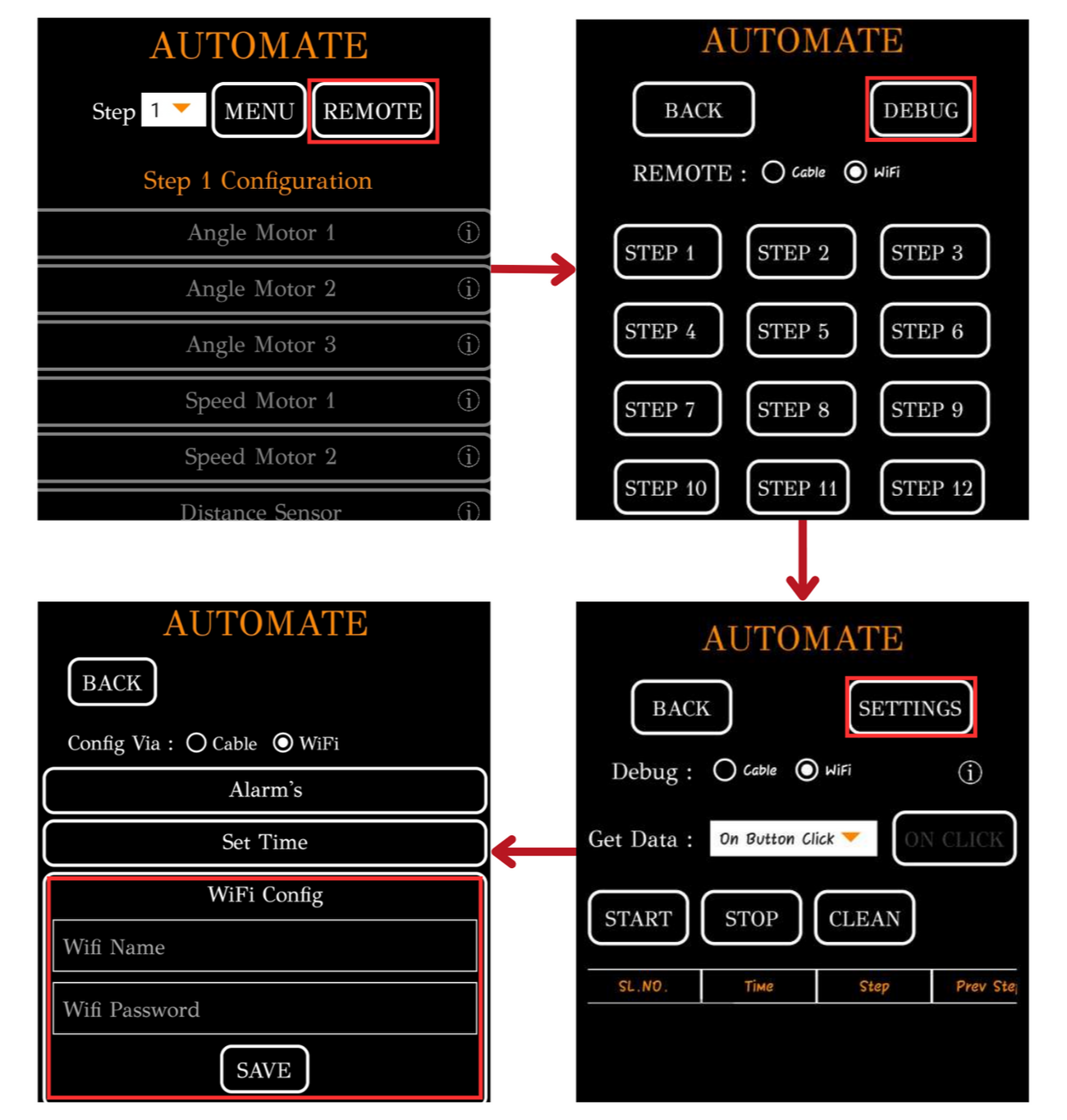
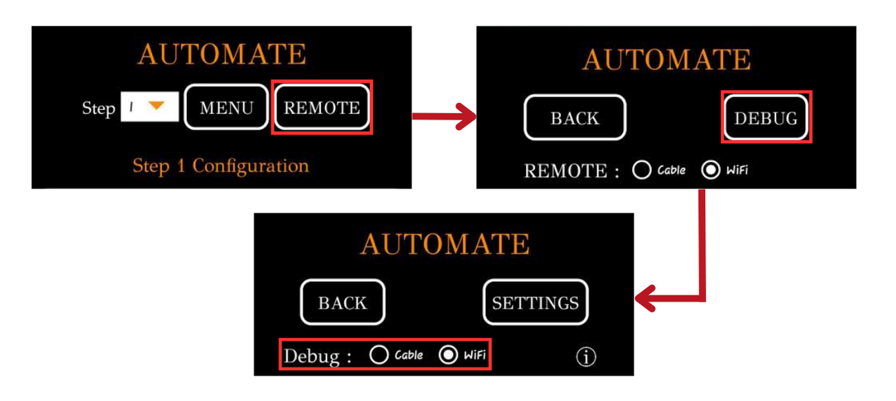
- Open the app, Go to Remote → Debug → Settings → Wi-fi Config. Change via Wi-fi or USB Cable
- The name of the Wi-Fi and Password should be exactly 8 characters.
Note: If more than one AUTOMATE kits are used nearby, Wi-Fi name and password change are recommended.
# 4. How to use debug feature in the Automate App?
Debugging is the process of identifying and removing errors/problems from the program.
- Open the Automate app, Go to Remote → Debug and select the mode of connection to the control unit. (Cable or WIFI)
- From the dropdown menu select how you want to get the data
- on button click – get the debug data when “on click” button is clicked.
- Time delay – get the debug data every X seconds. (say 1 second)
- On step change – get the debug data whenever step changes.
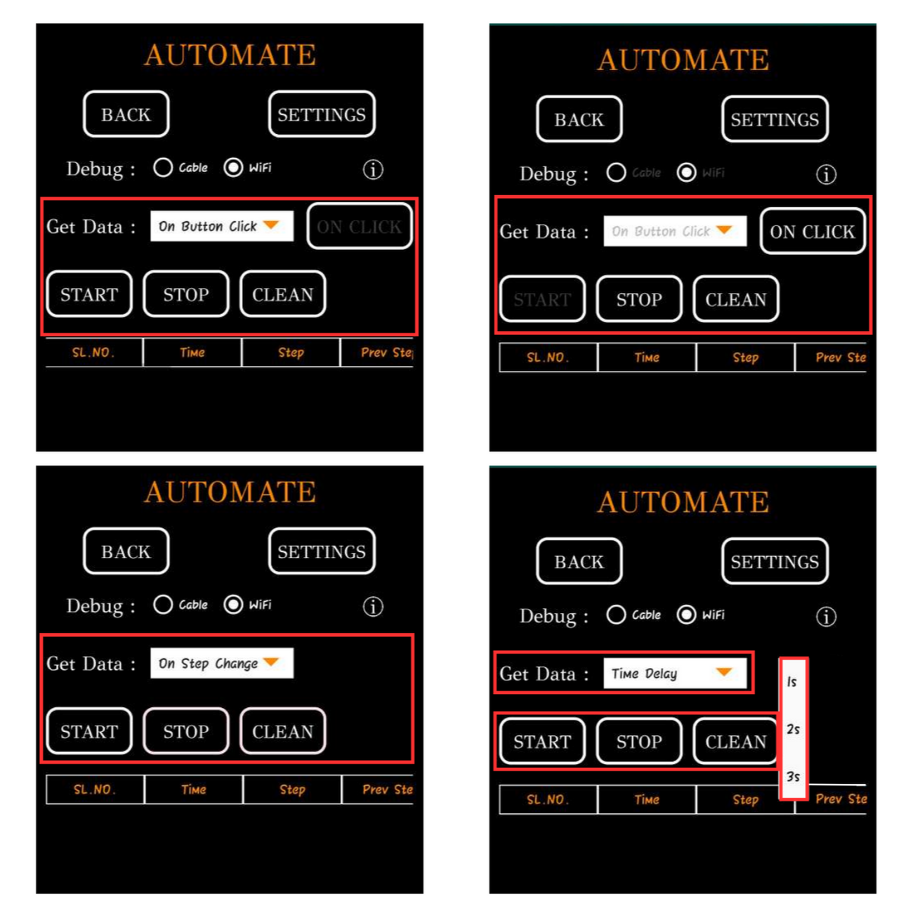
Now click on “START” button.
- If you have selected “on button click” option in the dropdown menu, you have to click “on click” button to get the data in the table
- If you have selected “time delay” or “on step change” the data will automatically be displayed in the table.
Click “STOP” button to stop receiving the data.
Click “CLEAN” button to clear the data displayed in the table.
From debug screen you can get the readings of
- Time
- Present step
- Previous step
- Step change reason
- Voltage input 1
- Voltage input 2
- Digital input 1
- Digital input 2
- Distance sensor
- Input voltage
# 5. How to use steps feature in the Automate App?
All the devices connected to the control unit can be configured to behave differently in different steps.
- There are 16 steps in total.
- At a given time, control card will only be in any one of the 16 steps.
- After the assigned tasks in a step are completed, you can either repeat the same step or jump to a different step.
- Step 1 is the starting step for any program.
- Each time when the control unit is turned on or new program is uploaded, there will be a delay of 5 seconds. After that, program will start from step 1 by default.
Refer to the App Manual Provided in the kit, for more information.
# 6. How does IR Sensor work and how to calibrate it ?
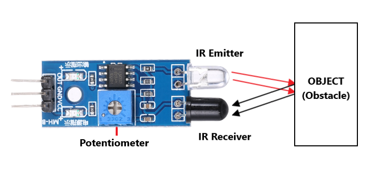
If the IR receiver detects some IR rays, the voltage input will detect X volts.
If the IR receiver didn’t detect IR rays, the voltage input will detect Y volts.
The amount of IR rays that gets reflected after hitting an object depends on the type of material. Some materials completely reflect the IR rays, some completely absorb the IR rays and some show both the characteristics. So, some testing has to be done on each type of material that you are going to use.
To calibrate IR sensor for black/white color detection,
- Connect the IR sensor to the Automate Control Unit using the sensor board.
- Place the IR sensor towards black and white coloured surface while accessing the debug feature in the Automate App and observe the voltage output for the sensor.
- The voltage output should vary while placing the IR sensor on these different colours. Usually 0.5V (may vary) for black colour and 0.2V (may vary) for white colour. This indicates the sensor is already calibrated.
- If the voltage output is same for the different colours, then place the IR sensor towards black colour surface and adjust the potentiometer to observe the voltage change (0.5V) in the debug feature.
- Repeat Step 2 and 3 again to verify whether the sensor is calibrated correctly or not.
- Set the Threshold voltage = Voltage observed while placing the sensor on top of the white colour surface.
# 7. How to calibrate Sound Sensor ?
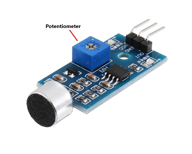
To Calibrate Sound Sensor,
- Connect the Sound Sensor to the Automate Control Unit via sensors board.
- Rotate the potentiometer (blue cube) in an anti-clockwise direction to its extreme end using a screwdriver, and then use the debug feature in the Automate App and locate the voltage output for the sensor. This voltage represents the minimum voltage output from the sensor.
- Set the Threshold voltage = Minimum voltage + 0.1V (varies according to ambient sounds), to be used throughout the projects.
# 8. How to calibrate PIR Sensor ?
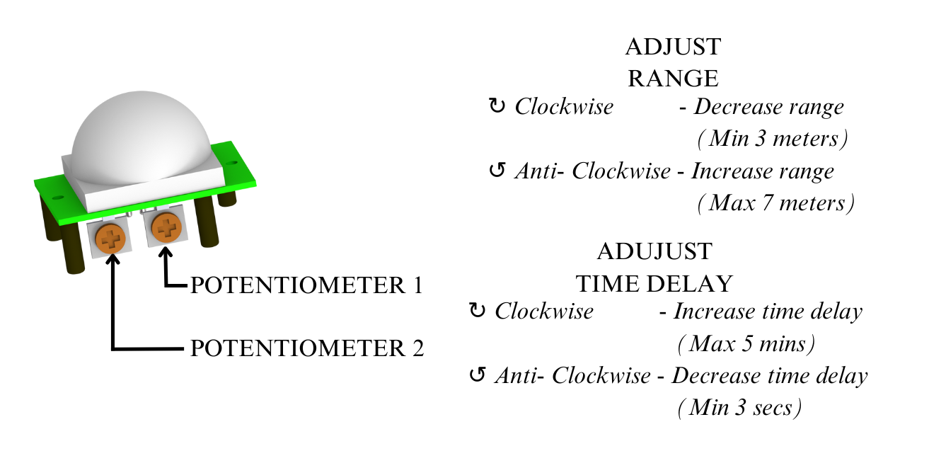
To Calibrate PIR sensor
- Connect the PIR sensor to the Automate Control Unit using the sensor board.
- Proceed to calibrate the sensor as follows: Rotate both the potentiometer in an anti-clockwise direction to its extreme end using a screwdriver.
- Next, access the debug feature in the Automate App and locate the voltage output for the sensor. This voltage represents the minimum voltage of the sensor.
- Set the Threshold voltage = Minimum voltage + 0.1V, to be used throughout the projects.
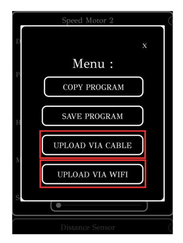
# 9. How to upload the program to the Control Unit with Automate App?
Make sure that the Automate App is connected to the Control Unit, before uploading the program.
To learn more, see How to connect the Automate App to the Control Unit ?
Click on the MENU button and then Click on the UPLOAD VIA CABLE / WIFI button to upload the program to the Control Unit.
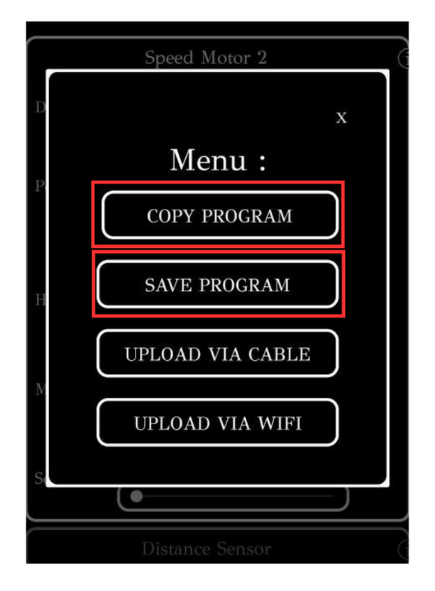
# 10. How to save the existing program or use the already saved program in the Automate App?
Click on the MENU button and
- Click on SAVE PROGRAM to save the configured program in mobile/windows.
- Click on COPY PROGRAM to use the saved program from mobile/windows.
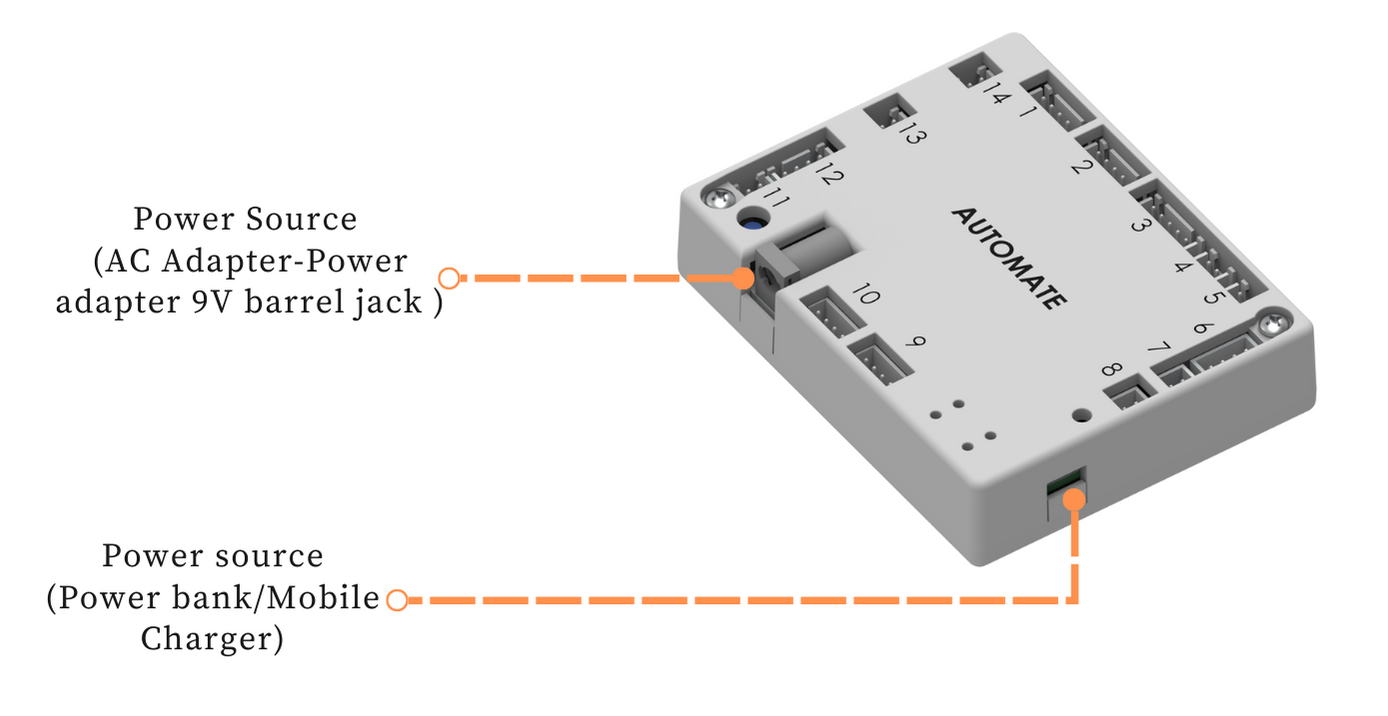
# 11. How to power the Control Unit?
Two options can be used to power the control unit:
- 5V micro-USB connector
- Power adapter 9V barrel jack
# 12. What devices can be connected to the Digital Output port in the Automate Control Unit?
Digital outputs will give 5V or 0V output. If you select blink option, it will change between 5V and 0V for every half second.
Devices that can be connected to digital outputs are LED Module, Buzzer Module & Relay.
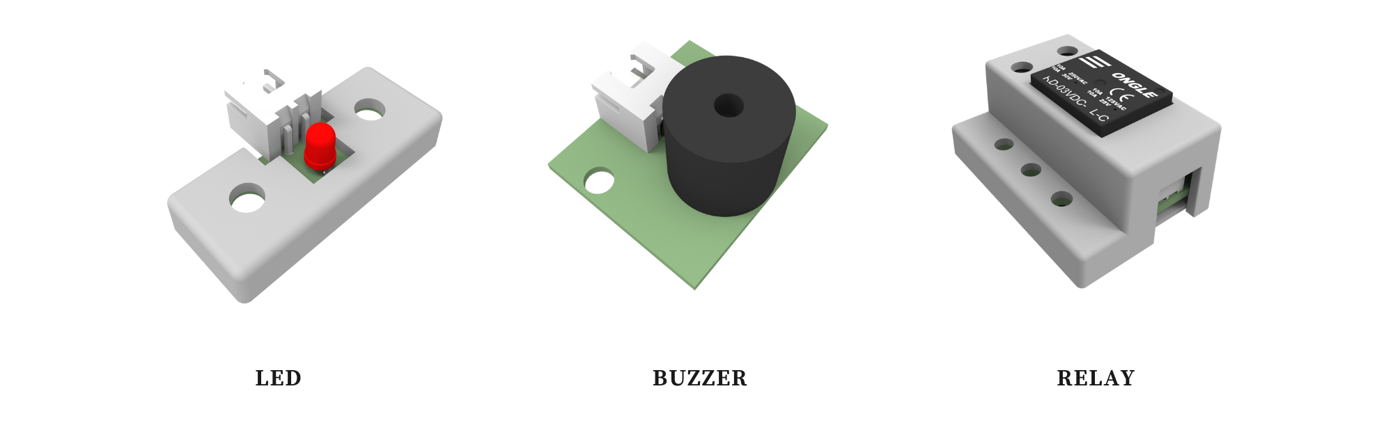
LED, buzzer or relay will be turned on when 5V is given, and turned off when 0V is given.
Note (what is a relay?): Relays are like normal switches used in your home for lights and fans. You can use relays instead of your regular switches. The only difference between them is that, instead of manually turning on or off, a relay can be turned on when 5 volts are given and turned off when 0 volt is given as input.
Disclaimer: All the activities which involves voltages greater than 50V should be performed under adult’s supervision.
# 13. What devices can be connected to Digital Input port in the Automate Control Unit?
Limit Switches can be connected to Digital Input ports.
- Digital inputs are used to detect the state of a switch (on/off).
- When the switch is on, the digital input will detect 5V.
- When the switch is off, the digital input will detect 0V.
- If the voltage sensed by the digital input is the same as what you selected, then the control card will jump to the selected step.
Note: Don’t forget to deactivate the digital input, when not used
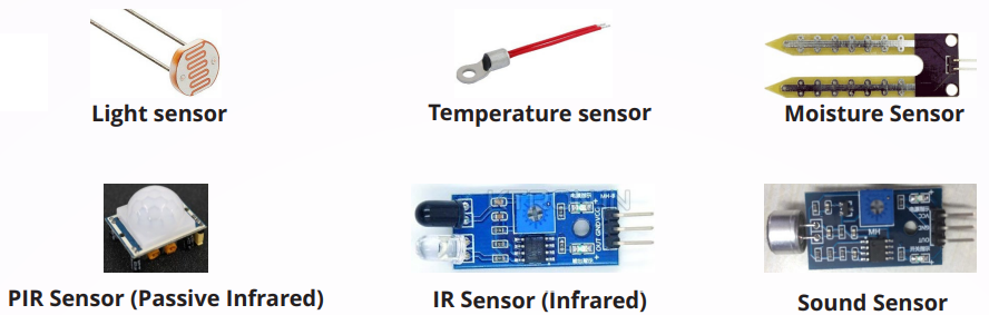
# 14. What sensors can be connected to the voltage input ports in Automate Control Unit?
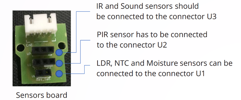
# 15. How to connect sensors to the voltage input ports in Automate Control Unit?
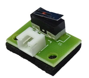
All these sensors must be connected to the control unit through the sensors board.
Note: Only one sensor must be connected to one sensor board at a time
The direction you connect IR, PIR and Sound sensors should match the below image
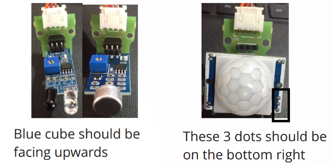
The direction doesn't matter for LDR, NTC and moisture sensors.
# 16. How do voltage input sensors provided in the Automate kit work?
Voltage Input sensors produce a voltage which can be sensed by the control unit. The voltage being sensed, gradually changes according to the parameters it is sensing.
- Light sensor – As the light falling on the sensor increases, the voltage read by the voltage input increases.
- Moisture sensor – As the moisture content increases, the voltage read by the voltage input increases.
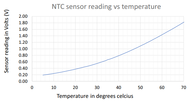
- Temperature sensor (NTC) – As the temperature increases, the voltage read by the voltage input increases.
- The remaining sensors (IR, PIR & Sound sensors) work a bit differently. They can give only two fixed voltages. If the parameter is not present, the voltage becomes low and if the parameter is present, the voltage becomes high.
The voltage given by a sensor can be found by connecting that sensor to the Automate Control Unit and then using the debug feature in Automate App.